Key Panels
Key Panels provide many basic functions for direct operator control and monitoring instead of machine operator control, a cost-effective, versatile and space

Overview
KeyPanel, empty front, at the back, not populated
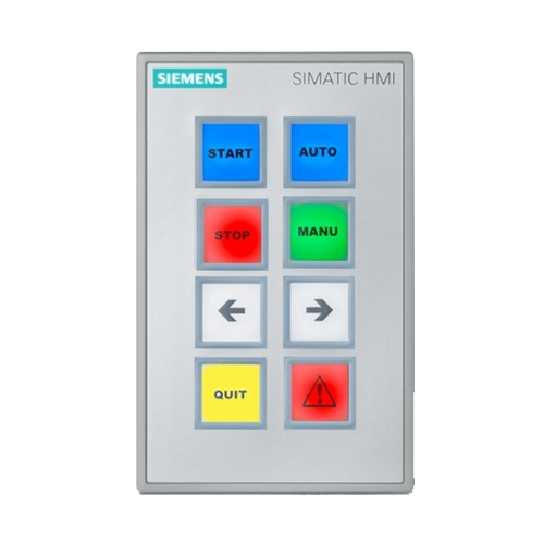
SIMATIC HMI Key Panels
- Optimum operability thanks to large mechanical keys and multi-colored LED backlighting (daylight readable)
- Over 60% time savings for wiring and installation (Plug&Play)
- More than 30% savings in material costs compared to conventional keypad operator panels
- 2 PROFINET ports (incl. switch) already integrated for setting up line and ring topologies
- Freely configurable digital I/Os on the rear for connecting key-operated switches, indicator lamps, etc.
- Connection of fail-safe emergency stop buttons or other fail-safe signals with KP8F and KP32F (in SIL2 or SIL3)
- Functionally compatible with all standard PROFINET master CPUs, also non-Siemens
- KP8 and empty front design, also optimized for installation in IPC Extension Units in IP65
- Maximum flexibility due to parameterization
- Empty front design for standardized assembly of flexible operator panels
- Installation enclosure, fully enclosed IP65, no drilling or milling necessary, KP8(F) not included; for accessories see technical specifications for installation enclosure
Benefits
- Less planning and assembly work than in the case of discrete components, thanks to the modular design
- Savings in hardware costs: Distributed I/O, 2 PROFINET connections and I/Os are combined in one device
- Keys and lamps can be labeled in IP65 using a standard printer (black and white or color)
- High flexibility due to freely configurable colors, switch/button function and integrated diagnostics function
- Any key color can be adapted dynamically to the process
- Integrated standard inputs and outputs for actuators and sensors, and each pin can be used as input or output
- Empty front designs can be used to reserve space for later system expansions and for easy mounting of standard 22.5 mm operator controls
- Functions and design are optimally matched in the SIMATIC HMI spectrum, e.g. in PRO device extension units
- SIL 2/3 safety with the “F” variants, e.g. emergency stop can be connected directly
For further details check the manual.
Application
- Ideally suited to most verticals (automotive, F&B to oil & gas) thanks to the smooth and rugged front, even in hazardous areas (see technical specifications)
- For intuitive, fast and very easy operation with minimum wiring
- Language-neutral feedback with multi-color LEDs in the keys, even readable in sunlight
- Extensions possible when built-in, without the need for cutting tools
- Special-purpose machine manufacturing benefits from the high degree of flexibility
Design
SIMATIC HMI Key Panel – Blank front design
- Simple seamless installation with mounting clips
- Rugged design, suitable for harsh industrial environments
- Prepared for installation of 22.5 mm standard components
- Easy installation, or retrofitting during operation, of standard 22.5 mm operator controls
- IP65 installation enclosure for KP8(F); 22.5 mm operator controls partially included
SIMATIC HMI Key Panel – Basic functions
- Smooth front, therefore easy to clean
- Large mechanical illuminated pushbutton units can be programmed as switches or buttons
- Loop-through 24 V DC power supply, no additional terminals required
- Two PROFINET interfaces, perfect for line operation
- Suitable for ring operation thanks to media redundancy protocol (MRP), normal running even when the PROFINET power supply cable is unplugged
- Inputs and outputs on the rear, each pin can be used as an input or an output
- The F variants are also equipped with SIL 2/3 inputs
SIMATIC HMI KP8 PN
- 8 large mechanical illuminated pushbuttons with extremely good tactile feedback, thus also suitable for harsh industrial environments
- 8 freely configurable digital I/Os
- For standard CPUs
SIMATIC HMI KP8F PN
- Additional digital fail-safe inputs for connecting single-channel or 1 x 2-channel sensors, such as emergency stop
- For fail-safe CPUs
SIMATIC HMI KP32F PN
- 32 large mechanical illuminated pushbuttons with extremely good tactile feedback, thus also suitable for harsh industrial environments
- 16 freely configurable digital I/Os
- Additional digital fail-safe inputs for connecting 4 x 1-channel or 2 x 2-channel sensors, such as emergency stop
- For fail-safe and standard CPUs
Demo case
SIMATIC HMI Key Panel – low-cost demo and experiment case.
The case consists of a KP8 PN with a 1211C CPU including demo program, set on a small plexiglas stand ready for use.
Can be ordered by fax:
Siemens AG, Mr. Michael Christ
Industry Sector, I IA CE SE MF RS FDS
Würzburger Str. 121, 90766 Fürth, Germany
Tel.: +49 911 750-4128 / Fax: +49 911 750-2411
- Inhalt:
- 1x case
- 1x KP8 PN
- 1x CPU1211C
- 1x stand, permanently wired, including program
- Power supply possible with a standard laptop mains adapter (not included in scope of supply) Prices and delivery times are available on request
Can be ordered by fax:
Siemens AG, Mr. Michael Christ
Industry Sector, I IA CE SE MF RS FDS
Würzburger Str. 121, 90766 Fürth, Germany
Tel.: +49 911 750-4128 / Fax: +49 911 750-2411
Technical specifications
Article Number | 6AV3688-3AY36-0AX0 | 6AV3688-3AF37-0AX0 | 6AV3688-3EH47-0AX0 | ||||||||||
|---|---|---|---|---|---|---|---|---|---|---|---|---|---|
SIMATIC HMI KP8 PN | SIMATIC HMI KP8F PN | SIMATIC HMI KP32F PN | |||||||||||
General information | |||||||||||||
Product type designation | KP8 PN | KP8F PN | KP32F PN | ||||||||||
Control elements | |||||||||||||
With parameterisable keys | Yes | Yes | Yes | ||||||||||
Keyboard fonts | |||||||||||||
● Membrane keyboard | |||||||||||||
— user-definable label membrane keys | Yes | Yes | Yes | ||||||||||
● Function keys | |||||||||||||
— Number of function keys | 8 | 8 | 32 | ||||||||||
● Short-stroke keys | |||||||||||||
— Number of short-stroke keys | 8 | 8 | 32 | ||||||||||
Expansions for operator control of the process | |||||||||||||
● DP direct LEDs (LEDs as S7 output I/O) | 8; Adjustable brightness | 8; Adjustable brightness | 8; Adjustable brightness | ||||||||||
● Number of color modes for LED | 5; Red, green, blue, yellow, white | 5; Red, green, blue, yellow, white | 5; Red, green, blue, yellow, white | ||||||||||
● Direct keys (keys as S7 input I/O) | 8 | 8 | 32 | ||||||||||
Installation type/mounting | |||||||||||||
Mounting type | Clamp terminals | Mounting clip | Mounting clip | ||||||||||
Mounting position | vertical | vertical | vertical | ||||||||||
Front mounting | Yes; Compatible with Extension Units dimensions | Yes; Compatible with Extension Units dimensions | Yes | ||||||||||
Rail mounting | No | No | No | ||||||||||
Wall mounting/direct mounting | No | No | No | ||||||||||
Mounting in portrait format possible | Yes | Yes | Yes | ||||||||||
Mounting in landscape format possible | Yes | Yes | Yes | ||||||||||
maximum permissible angle of inclination without external ventilation | 30°; To the front/rear | 30°; To the front/rear | 30°; To the front/rear | ||||||||||
Number of slots for command devices and signaling units | 0 | 0 | 0 | ||||||||||
Supply voltage | |||||||||||||
Type of supply voltage | DC | DC | DC | ||||||||||
Rated value (DC) | 24 V; 24 V looped through at connector, no interruption on pulling | 24 V; 24 V can be looped through connector, interrupted when pulled | 24 V; 24 V looped through at connector, no interruption on pulling | ||||||||||
permissible range, lower limit (DC) | 20.4 V | 20.4 V | 20.4 V | ||||||||||
permissible range, upper limit (DC) | 28.8 V | 28.8 V | 28.8 V | ||||||||||
Input current | |||||||||||||
Current consumption (rated value) | 0.3 A | 0.3 A | 1 A | ||||||||||
Type of output | |||||||||||||
LED colors | |||||||||||||
● red | Yes | Yes | Yes | ||||||||||
● yellow | Yes | Yes | Yes | ||||||||||
● green | Yes | Yes | Yes | ||||||||||
● white | Yes | Yes | Yes | ||||||||||
● blue | Yes | Yes | Yes | ||||||||||
Digital inputs | |||||||||||||
Number of digital inputs | 8; Max. 8 inputs and outputs (total) | 8; Total inputs and outputs max. 8 and 1x SIL 2 or 2x SIL 3 | 32; Total inputs and outputs max. 32 and 2x SIL 2 or 4x SIL 3 | ||||||||||
Input voltage | |||||||||||||
● Rated value (DC) | 24 V | 24 V | 24 V | ||||||||||
Digital output | |||||||||||||
Number of digital outputs | 8; Max. 8 inputs and outputs (total) | 8; Max. 8 inputs and outputs (total) | 16; Max. 32 inputs and outputs (total) | ||||||||||
Short-circuit protection | Yes | Yes | Yes | ||||||||||
Switching capacity of the outputs | |||||||||||||
● with resistive load, max. | 100 mA | 100 mA | 100 mA | ||||||||||
Output voltage | |||||||||||||
● Rated value (DC) | 24 V; Non-isolated | 24 V; Non-isolated | 24 V; Non-isolated | ||||||||||
Total current of the outputs | |||||||||||||
● Current per channel, max. | 100 mA | 100 mA | 100 mA | ||||||||||
● Current per group, max. | 800 mA | 800 mA | 800 mA | ||||||||||
Interfaces | |||||||||||||
Number of industrial Ethernet interfaces | 2; For the construction of lines and rings without external switch | 2; For the construction of lines and rings without external switch | 2; For the construction of lines and rings without external switch | ||||||||||
Number of PROFINET interfaces | 2; Incl. switch | 2; Incl. switch | 2; Incl. switch | ||||||||||
Industrial Ethernet | |||||||||||||
● Industrial Ethernet status LED | 2; Per port | 2; Per port | 2; Per port | ||||||||||
● Number of ports of the integrated switch | 2; Per port | 2; Per port | 2; Per port | ||||||||||
Protocols | |||||||||||||
PROFINET | Yes; also 3rd party PLC | Yes; also 3rd party PLC | Yes; incl. shared device, 3rd party PLC | ||||||||||
Supports protocol for PROFINET IO | Yes | Yes | Yes | ||||||||||
PROFINET CBA | No | No | No | ||||||||||
IRT | Yes | Yes | Yes | ||||||||||
PROFIsafe | No | Yes; 1x SIL 3 (two-channel) or 2x SIL 2 (single-channel) emergency stop sensors | Yes; 2x SIL 3 (two-channel) or 4x SIL 2 (single-channel) emergency stop sensors | ||||||||||
PROFIBUS | No | No | No | ||||||||||
MPI | No | No | No | ||||||||||
AS-Interface | No | No | No | ||||||||||
EIB/KNX | No | No | No | ||||||||||
Protocols (Ethernet) | |||||||||||||
● TCP/IP | No | No | No | ||||||||||
Redundancy mode | |||||||||||||
● MRP | Yes | Yes | Yes | ||||||||||
Further protocols | |||||||||||||
● AS-Interface Safety at Work | No | No | No | ||||||||||
● CAN | No | No | No | ||||||||||
● Data-Highway | No | No | No | ||||||||||
● DeviceNet | No | No | No | ||||||||||
● DeviceNet Safety | No | No | No | ||||||||||
● EtherNet/IP | No | No | No | ||||||||||
● Foundation Fieldbus | No | No | No | ||||||||||
● INTERBUS | No | No | No | ||||||||||
● INTERBUS-Safety | No | No | No | ||||||||||
● Local Operating Network | No | No | No | ||||||||||
● MODBUS | No | No | No | ||||||||||
● SafetyBUS p | No | No | No | ||||||||||
● SERCOS | No | No | No | ||||||||||
● other bus systems | No | No | No | ||||||||||
Test commissioning functions | |||||||||||||
Illuminant test | Yes; During switch on | Yes; During switch on | Yes; During switch on | ||||||||||
Key and signal lamp test | Yes; Automatically when switching on | Yes; Automatically when switching on | Yes; Automatically when switching on | ||||||||||
EMC | |||||||||||||
Emission of radio interference acc. to EN 55 011 | |||||||||||||
● Limit class A, for use in industrial areas | Yes; Group 1, measured at a distance of 10 m | Yes; Group 1, measured at a distance of 10 m | Yes; Group 1, measured at a distance of 10 m | ||||||||||
● Limit class B, for use in industrial areas | No | No | No | ||||||||||
Degree and class of protection | |||||||||||||
IP (at the front) | IP65 | IP65 | IP65 | ||||||||||
Enclosure Type 4 at the front | No | No | No | ||||||||||
Enclosure Type 4x at the front | Yes; Incl. NEMA12 | Yes; Incl. NEMA12 | Yes; Incl. NEMA12 | ||||||||||
IP (rear) | IP20 | IP20 | IP20 | ||||||||||
Standards, approvals, certificates | |||||||||||||
CE mark | Yes | Yes | Yes | ||||||||||
cULus | Yes | Yes | Yes | ||||||||||
RCM (formerly C-TICK) | Yes | Yes | Yes | ||||||||||
KC approval | Yes | Yes | Yes | ||||||||||
CCC | No; not necessary | No; not necessary | |||||||||||
Suitable for safety functions | No | Yes | Yes | ||||||||||
Use in hazardous areas | |||||||||||||
● ATEX Zone 2 | Yes | Yes | No | ||||||||||
● ATEX Zone 22 | Yes | Yes | No | ||||||||||
● cULus Class I Zone 1 | No | No | No | ||||||||||
● cULus Class I Zone 2, Division 2 | Yes | Yes | No | ||||||||||
● FM Class I Division 2 | Yes | Yes | No | ||||||||||
Marine approval | |||||||||||||
● Germanischer Lloyd (GL) | No | No | No | ||||||||||
● American Bureau of Shipping (ABS) | No | No | No | ||||||||||
● Bureau Veritas (BV) | No | No | No | ||||||||||
● Det Norske Veritas (DNV) | No | No | No | ||||||||||
● Lloyds Register of Shipping (LRS) | No | No | No | ||||||||||
● Nippon Kaiji Kyokai (Class NK) | No | No | No | ||||||||||
● Polski Rejestr Statkow (PRS) | No | No | No | ||||||||||
Ambient conditions | |||||||||||||
Ambient temperature during operation | |||||||||||||
● min. | 0 °C | 0 °C | 0 °C | ||||||||||
● max. | 55 °C | 55 °C | 55 °C | ||||||||||
● Operation (vertical installation) | |||||||||||||
— For vertical installation, min. | 0 °C | 0 °C | 0 °C | ||||||||||
— For vertical installation, max. | 55 °C | 55 °C | 55 °C | ||||||||||
● Operation (max. tilt angle) | |||||||||||||
— At maximum tilt angle, min. | 0 °C | 0 °C | 0 °C | ||||||||||
— At maximum tilt angle, min. | 45 °C | 45 °C | 45 °C | ||||||||||
● Operation (vertical installation, portrait format) | |||||||||||||
— For vertical installation, min. | 0 °C | 0 °C | 0 °C | ||||||||||
— For vertical installation, max. | 55 °C | 55 °C | 55 °C | ||||||||||
● Operation (max. tilt angle, portrait format) | |||||||||||||
— At maximum tilt angle, min. | 0 °C | 0 °C | 0 °C | ||||||||||
— At maximum tilt angle, min. | 45 °C | 45 °C | 45 °C | ||||||||||
Ambient temperature during storage/transportation | |||||||||||||
● min. | -20 °C | -20 °C | -20 °C | ||||||||||
● max. | 60 °C | 60 °C | 60 °C | ||||||||||
Relative humidity | |||||||||||||
● Operation, max. | 95 %; no condensation | 95 %; no condensation | 95 %; no condensation | ||||||||||
Configuration | |||||||||||||
Configuration software | |||||||||||||
● STEP 7 Basic (TIA Portal) | Yes | Yes | Yes | ||||||||||
● STEP 7 Professional (TIA Portal) | Yes | Yes | Yes | ||||||||||
Use in hazardous areas | |||||||||||||
Frequently Asked Questions (FAQs)
Build innovative machines faster without costly prototyping with Efficient Motion Control.
With Effective Motion Control, machine builders can easily overcome major challenges and enable faster time-to-market, increased functionality, resolve complex system requirements, and demands for safety and sustainability.

We are Siemens trusted and approved distribution partner.
As a Value Added Reseller in Siemens’ Approved Partner network, Parmley Graham is a proven supplier of a wide range of quality products in the UK and globally.
Find out more how this will benefit you or check Siemens Configurator.